
Key takeaways
- Hydraulic symbols provide a standard visual language for circuits, reducing misinterpretation.
- Lines indicate flow paths; arrows show direction; dashed lines mark pilot or drain functions.
- Pump and motor symbols distinguish energy input versus output using arrow orientation.
- Valve symbols show normal positions, actuation methods, and the number of ports.
- Pressure control symbols identify relief, reducing, and sequence functions by spring settings.
- Filter, cooler, and accumulator symbols highlight conditioning and energy storage points.
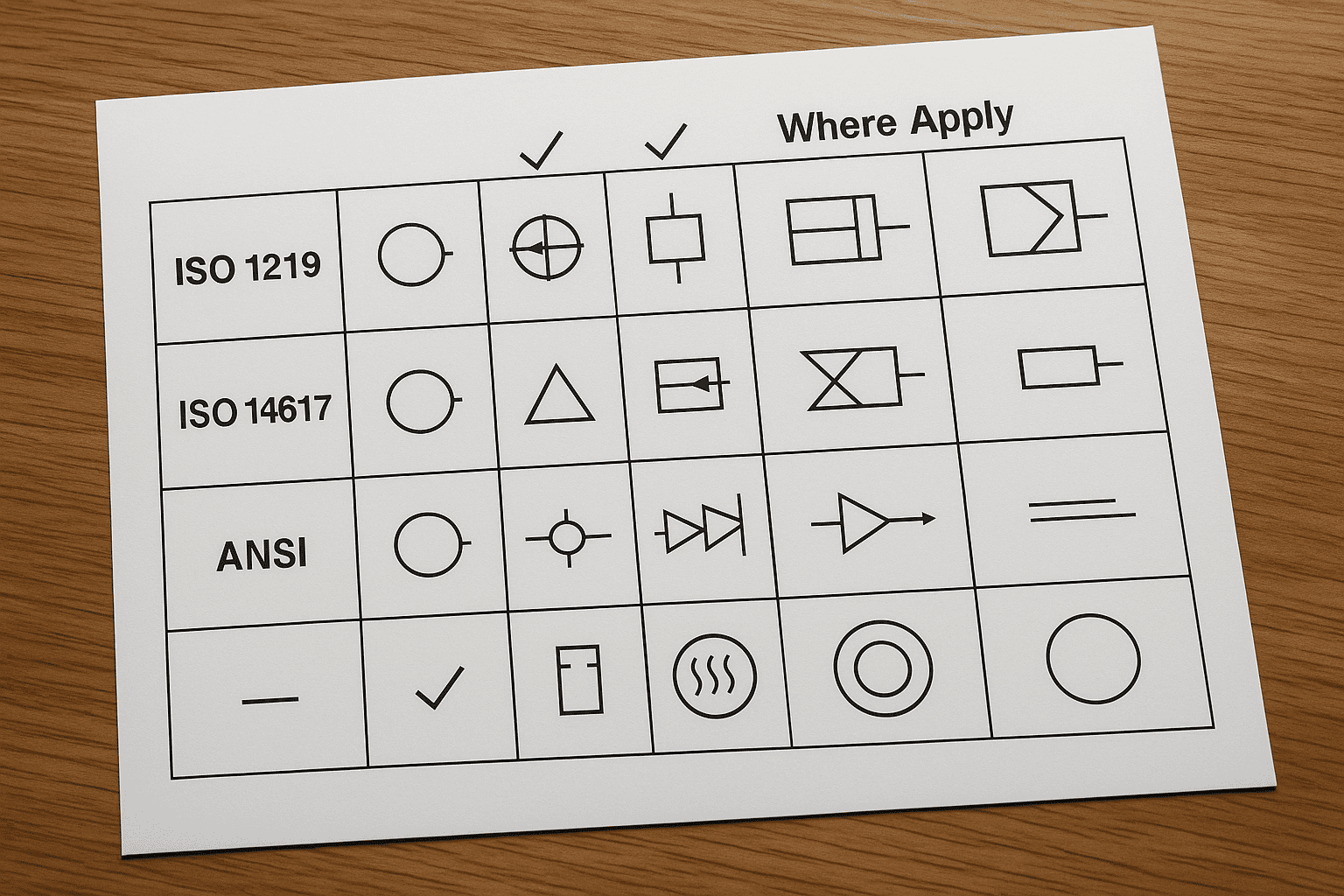
Hydraulic Symbol Standards and Where They Apply (ISO 1219, ISO 14617, ANSI)
ISO published ISO 1219-1:2012 to standardise hydraulic and pneumatic symbols, and the document spans 2 parts (Part 1 for graphical symbols and Part 2 for circuit diagrams). That scope matters because a single misread symbol can change a valve’s function from normally closed to normally open, altering system behaviour at operating pressures that commonly exceed 200 bar in industrial hydraulics. Standard symbols reduce interpretation errors when drawings move between design, procurement, and maintenance teams. ISO 1219 applies most directly to fluid power circuit diagrams used in machine design and commissioning, especially when suppliers and integrators work across borders. For broader engineering documentation, ISO 14617 provides a multi-domain symbol library that covers fluid power alongside electrical and instrumentation notation, which helps when a schematic combines hydraulic actuation with 24 V control circuits and sensor feedback. In North America, ANSI practices often align with ISO but appear through sector standards and legacy drafting conventions; many US prints still reference ANSI-style symbol usage for valves, pumps, and actuators. When selecting a standard, match it to the deliverable: ISO 1219 for hydraulic schematics, ISO 14617 for cross-discipline diagrams, and ANSI-aligned conventions when servicing installed equipment built to US documentation norms.
Hydraulic Symbol Standards and Where They Apply (ISO 1219, ISO 14617, ANSI)
How to Read a Hydraulic Schematic: Lines, Junctions, Crossovers, and Reference Designators
A maintenance engineer traces a slow cylinder on a press and sees a line crossing another line near a valve bank. The drawing shows no dot at the crossing, yet a nearby junction includes a solid dot. That small difference decides whether flow reaches the cylinder or passes straight through to tank, which can mean the difference between a 6-second extend and a 20-second extend at a typical 210 bar system setting. Read the schematic by treating lines as the “plumbing” of the diagram. A continuous line represents a hydraulic connection, while a dashed pilot line indicates a control signal rather than main flow. When two lines meet with a filled junction dot, the circuit connects at that node; without a dot, the lines only cross visually. Many drawings use a crossover “bridge” or hump to make the non-connection explicit, reducing misreads during fault-finding. Reference designators then anchor symbols to real hardware. A valve labelled V2 or a pump labelled P1 should match the equipment list and the tags on the machine, so a technician can move from paper to manifold in minutes, not hours. ISO conventions for circuit diagrams in ISO 1219-2 support this mapping, which becomes critical when a manifold contains 12–24 cartridges with similar outlines.
Hydraulic Power Sources: Pumps, Prime Movers, Reservoirs, and Power Units
Schematics may show a pump as fixed displacement with near-constant flow, or variable displacement that trims flow to demand. The drive matters too: an electric motor holds speed, while a diesel engine varies speed, shifting pump output and heat load.
| Symbol group | Option A | Option B | What changes in practice |
|---|---|---|---|
| Pumps | Fixed displacement | Variable displacement | Flow stays proportional to speed versus flow trims to maintain pressure or limit power. |
| Prime movers | Electric motor | Diesel engine | Stable speed versus speed droop; expect different start-up behaviour and noise constraints. |
| Reservoirs | Vented tank | Pressurised tank | Lower cost and simpler maintenance versus improved inlet conditions and reduced cavitation risk. |
| Power units | Integrated hydraulic power unit (HPU) | Distributed pump and tank | Faster installation and standardised layouts versus flexible placement and shorter suction lines. |
Symbols often signal control intent. A variable pump symbol usually implies a compensator that can hold about 210 bar while reducing flow at idle, cutting wasted power versus a fixed pump circulating oil through a relief valve. Reservoir symbols affect fault-finding: a pressurised tank can hide suction leaks that show quickly on a vented tank. If a drawing shows an HPU, expect a packaged unit with pump, prime mover, reservoir, filtration, and cooling sized together; many industrial HPUs run 20–200 L/min. For common symbol definitions, consult ISO 1219-1 and NFPA fluid power documentation.
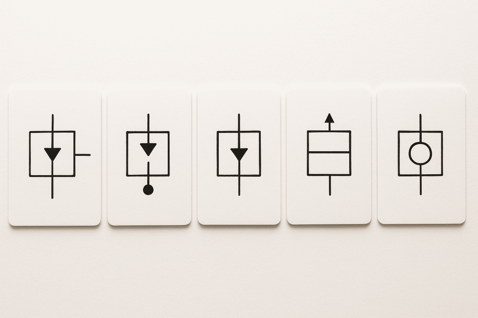
Pressure Control Symbols: Relief, Reducing, Sequence, Unloading, and Counterbalance Valves
Pressure Control Symbols: Relief, Reducing, Sequence, Unloading, and Counterbalance Valves
Pressure-control symbols cause costly faults because small graphic cues change the valve’s job. A relief valve symbol limits maximum pressure, while a reducing valve symbol maintains lower downstream pressure; confusing the two can push an actuator above its rated limit. In a 210 bar circuit, a 10% setting error raises peak pressure by 21 bar, often triggering nuisance trips or seal damage. Use a quick method: read the flow path, then confirm the control action shown by the spring, pilot line, and drain. Relief symbols show a pressure-to-tank path that opens at a setpoint. Reducing symbols sense downstream pressure and throttle to hold 120 bar while upstream remains at 210 bar. Sequence symbols resemble relief valves but route flow to a secondary function after reaching a set pressure. Unloading symbols vent pump flow to tank once an accumulator reaches cut-out pressure. Counterbalance symbols show a pilot-assisted restriction that prevents overrunning loads and often needs a 3:1 pilot ratio for stable opening. After identification, verify the setpoint note, check for an external drain marking, and match the pilot source to the correct line. Confirm symbol conventions against ISO 1219-1 when drawings mix suppliers.
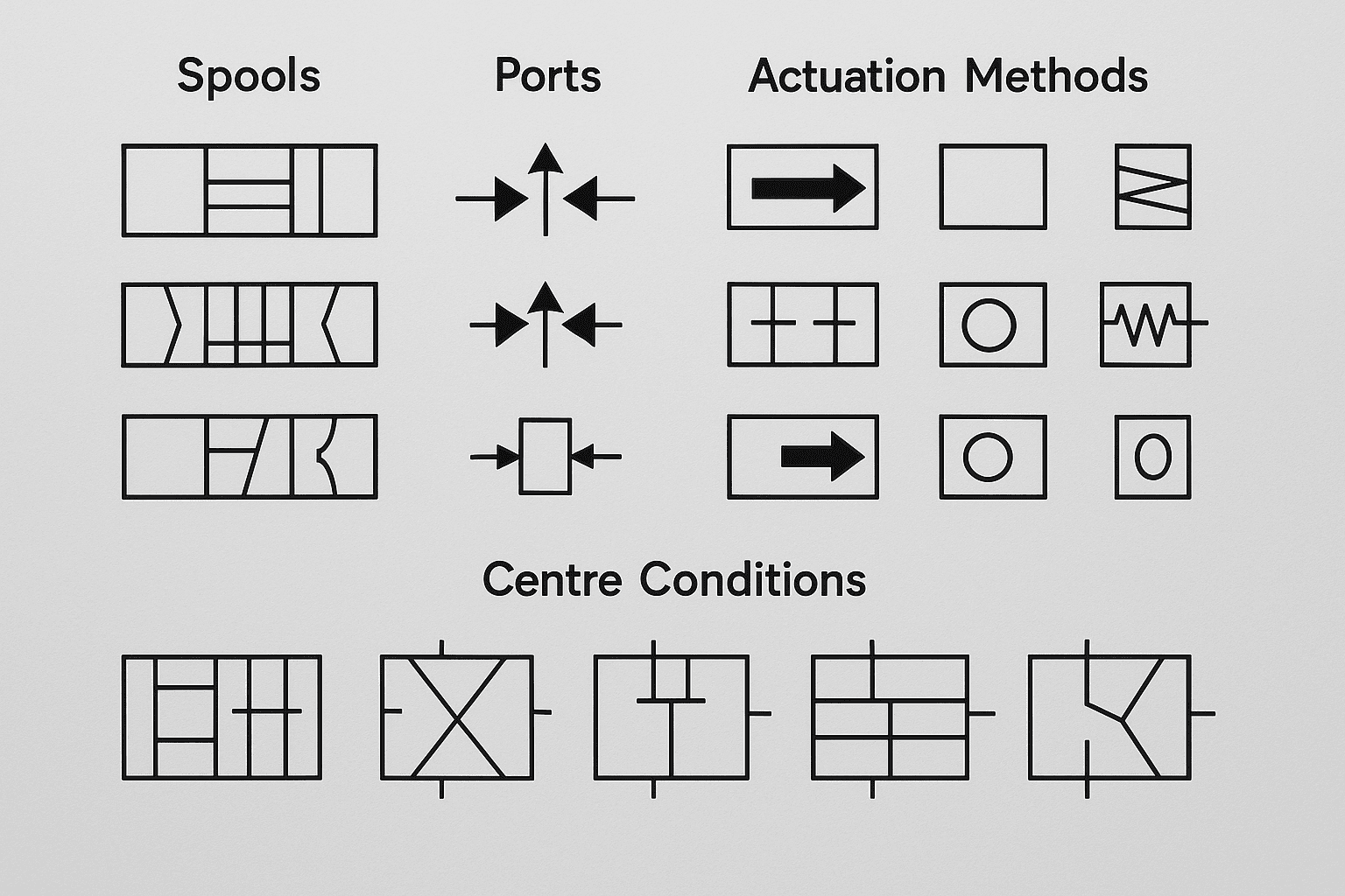
Directional Control Valve Symbols: Spools, Ports, Actuation Methods, and Centre Conditions
ISO directional control valve symbols show 2–4 adjacent boxes to indicate spool positions, and the port count commonly ranges from 2 (2/2) to 5 (5/3). Each box maps internal flow paths between P, T, A, and B, so a single position change can reverse a cylinder or unload a pump. Actuation marks identify how the spool shifts: a solenoid coil typically operates on 24 V DC, while a spring symbol shows automatic return to a default state. Centre conditions on 3-position valves (closed, open, tandem, float) define neutral behaviour, affecting standby pressure and heat generation.
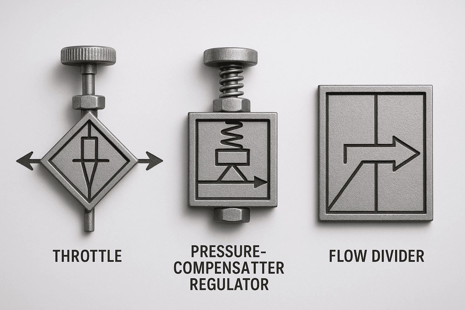
Flow Control Symbols: Throttles, Pressure-Compensated Regulators, and Flow Dividers
Flow Control Symbols: Throttles, Pressure-Compensated Regulators, and Flow Dividers
A packaging line runs 60 cartons per minute, but the sealing cylinder starts slamming at the end of stroke after a product change. The schematic shows a flow control symbol in the extend line: a variable throttle with a check valve bypass, set to meter-out. That symbol matters because restricting return flow stabilises motion under load, while a meter-in throttle can allow run-away when the load drives the actuator. When the load varies, a simple throttle symbol signals a speed change with pressure: as differential pressure rises, flow drops and the cylinder slows. A pressure-compensated flow regulator symbol adds a compensator element, indicating near-constant flow across a range of inlet pressures, often 70–210 bar in industrial circuits, which keeps cycle time consistent after a tooling swap. Flow divider symbols extend the idea to synchronisation. The symbol indicates one inlet feeding two controlled outlets, used to keep twin cylinders within a few millimetres on a lift table, even when friction differs side to side. ISO symbol conventions for these devices follow ISO 1219, so the compensator and divider cues remain consistent across drawings.
Non-Return and Logic Elements: Check Valves, Shuttle Valves, and Pilot-Operated Checks
A check valve symbol shows one-way flow, often with a spring-loaded poppet. A shuttle valve symbol shows two inlets feeding one outlet via a moving ball or spool. A pilot-operated check adds a pilot line, showing that pressure can release the lock. These cues separate backflow prevention from load holding and logic selection.
| Element | What the symbol indicates | Typical use case | Common misread consequence |
|---|---|---|---|
| Check valve (non-return) | Free flow in one direction; blocked in reverse, often with a spring mark | Prevent reverse flow to protect pumps and maintain prime | Reverse flow can unload an actuator and increase cycle time |
| Shuttle valve (OR logic) | Two inlets; one outlet; internal shuttle selects the higher-pressure supply | Select between two pilot signals, such as manual override versus automatic control | Incorrect logic can energise the wrong function under transient pressure |
| Pilot-operated check | Check valve plus pilot port; pilot pressure opens the check against load pressure | Lock a cylinder to hold a suspended load, then release under command | Missing the pilot line can trap pressure and prevent retraction |
Check valves suit circuits where reverse flow must not occur, while shuttle valves suit control circuits where either signal may command an action. Pilot-operated checks suit load holding but need adequate pilot ratio; many designs use 3:1 to 4:1, so a 200 bar load may need 50–70 bar pilot pressure to release. Align drawings with ISO 1219-1 conventions so technicians read pilot lines, springs, and flow paths consistently.
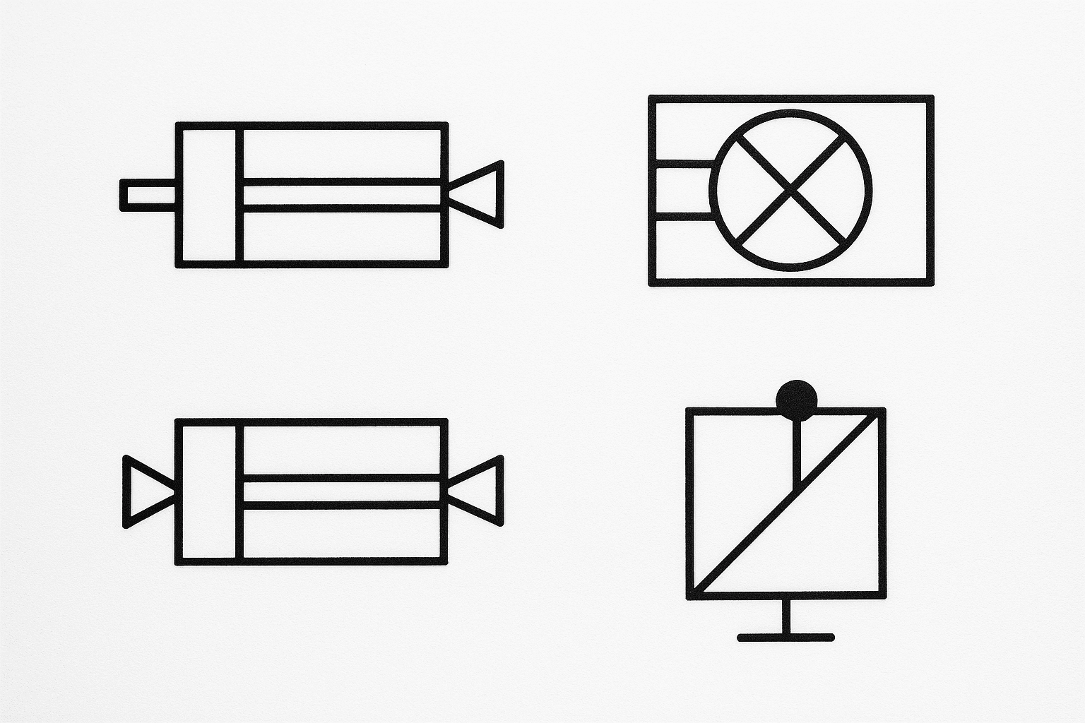
Actuator Symbols: Cylinders, Hydraulic Motors, Cushions, and Load-Holding Features
Actuator Symbols: Cylinders, Hydraulic Motors, Cushions, and Load-Holding Features
Actuator symbols cause commissioning delays because small graphic differences change motion, force, and safety. A common failure occurs when a technician reads a single-acting cylinder as double-acting, then connects two hoses to a cylinder with one pressure port. On a 210 bar system, trapped oil can spike pressure above the relief setting and damage rod seals within minutes. Another frequent error confuses a hydraulic motor with a rotary actuator or pump, which can reverse rotation and stall a conveyor drive at start-up.
Solution: read actuator symbols as “function blocks”
Use a consistent method: identify the actuator type, then confirm how the symbol shows ports, stroke limits, and load-holding features. ISO actuator symbols follow ISO 1219 conventions, so the drawing usually encodes three decisions: linear versus rotary motion, number of working ports, and whether the actuator includes end-of-stroke control or locking. When the schematic includes reference designators, treat the actuator tag as the anchor point for tracing A and B lines back to the directional valve.
Implementation steps: cylinders, motors, cushions, and load holding
Start with cylinders. A double-acting cylinder shows two working ports for powered extend and retract. A single-acting cylinder shows one working port and a spring or external load return, so retract force depends on spring rate or gravity rather than hydraulic pressure. If the symbol shows a rod on one side, areas differ, so extend and retract speeds differ at the same pump flow (for example, 20 L/min often produces faster retract on a single-rod cylinder). Move to rotary actuators. A hydraulic motor symbol indicates continuous rotation, while a rotary actuator implies limited angular travel. Check for case drain markings; many industrial motors need a separate drain to tank to protect shaft seals, and omitting that line often causes leakage within the first 10–50 operating hours. Verify cushions and deceleration features. Cushion symbols at cylinder ends indicate controlled restriction near end of stroke, reducing impact energy and noise. If the symbol shows adjustable cushioning, run the axis at normal speed, close the adjuster until the cylinder slows in the last 10–30 mm, then open slightly to prevent stick-slip. Finish with load-holding features. A pilot-operated check or counterbalance element near the actuator indicates the circuit prevents run-away or drift under load. Treat that symbol as safety-critical: confirm pilot line routing, verify cracking pressure settings, and measure drift under load over 5 minutes.
Results: faster fault isolation and safer motion
When teams apply this read-order, fault isolation improves because each symbol answers a specific question before hoses move. Correcting actuator interpretation removes repeat faults such as end-stroke banging and load drop, and it shortens set-up time by one to two troubleshooting cycles per axis. The outcome is predictable motion, lower peak pressures, and fewer seal and hose failures during the first week of operation.
Filtration, Cooling, and Accumulators: Condition Control and Energy Storage Symbols
Contamination drives a large share of hydraulic failures: ISO 4406 cleanliness targets often sit around 18/16/13 for general industrial systems, while servo-grade circuits commonly specify 16/14/11 or cleaner (ISO). Those numbers matter because the filtration symbol does more than mark a filter location; it signals whether the element sits on suction, pressure, or return, and whether a bypass path can protect the pump during cold starts. A bypass setting of 1.5–2.0 bar can prevent element collapse, but it also allows unfiltered flow if the symbol indicates a bypass valve. Cooling symbols control temperature, which directly affects viscosity and leakage. Mineral hydraulic oil typically performs best around 40–60 °C; above 70 °C, oxidation accelerates and seal life drops sharply. The cooler symbol distinguishes air-oil from water-oil exchangers, and the presence of a thermostatic bypass mark indicates that the circuit can warm up quickly before sending flow through the core. Accumulator symbols represent stored energy and safety risk. A bladder or piston accumulator commonly precharges to 0.9× the minimum working pressure, and many designs limit usable volume to roughly 30–40% of the nominal gas volume to avoid excessive pressure swing. ISO symbol cues for gas charge and isolation hardware align with ISO 1219 conventions and help technicians identify where to depressurise before maintenance.
Common Symbol Misreads and Troubleshooting: Typical Errors, Verification Steps, and Best Practices
A maintenance team replaces a 4/3 directional valve on a press, then finds the ram creeping down during a 30-second hold. The schematic appears to show a pilot-operated check, but the “pilot” line actually indicates an external drain; the circuit never locks the load. Verify the symbol by tracing every reference designator to the valve’s port letters, then cross-check the manufacturer’s datasheet and the ISO graphic rules in ISO 1219. Apply the same discipline to any ambiguous mark: confirm line type (pilot, drain, or case), confirm default positions, then test at low pressure before returning to 210 bar service.
Frequently Asked Questions
What do hydraulic symbols represent on ISO 1219 hydraulic circuit diagrams?
On ISO 1219 hydraulic circuit diagrams, hydraulic symbols represent components and functions using standardised shapes. Symbols show the type of element (pump, valve, actuator), its normal position, flow paths, and how it operates (manual, mechanical, hydraulic, or electrical actuation). The notation also indicates connections, ports, and directional control states.
How do you distinguish between fixed-displacement and variable-displacement pump symbols on a schematic?
On ISO 1219 schematics, both pumps use a circle with a filled triangle pointing outwards. A fixed-displacement pump shows only that basic symbol. A variable-displacement pump adds a diagonal arrow through the circle, indicating adjustable flow per revolution. When the arrow ends with a control mark, it indicates pressure or load compensation.
What is the difference between a pressure relief valve symbol and a pressure reducing valve symbol?
A pressure relief valve symbol shows a valve that opens to tank when pressure exceeds a set value, protecting the circuit from overpressure. A pressure reducing valve symbol shows a normally open valve that throttles to maintain a lower, controlled downstream pressure, often with a pilot line sensing outlet pressure. Relief controls maximum pressure; reducing controls branch pressure.
How do directional control valve symbols indicate the number of ports, positions, and actuation method?
Directional control valve symbols use adjacent squares to show positions: two squares mean 2-position, three mean 3-position. Port count appears as external connection lines to the envelope; each line represents one port (for example, 4 lines for a 4-way valve). Actuation appears as end symbols, such as a solenoid coil, lever, pedal, or spring return.
What do hydraulic line and connection symbols mean, including pilot lines, drain lines, and cross-port connections?
Hydraulic line symbols show how fluid or signals travel between components. Solid lines indicate main pressure/return flow; dashed or dotted lines indicate pilot (control) lines. Drain lines use a separate, low-pressure return path to tank, often shown as a thin or dashed line. Cross-port connections link opposite actuator ports to balance pressure or enable anti-cavitation flow.