
Pipe size charts and pipe schedule charts help engineers, installers, and buyers select pipe that fits both flow requirements and pressure ratings. Nominal Pipe Size (NPS) labels the pipe, while the schedule number indicates wall thickness, which changes the internal diameter and weight. For example, a 2-inch pipe in Schedule 40 has a thicker wall than Schedule 10, reducing bore size. This guide summarises common sizes, schedules, and practical selection checks.
Key takeaways
- Nominal Pipe Size (NPS) labels do not equal the pipe’s actual outside diameter.
- Pipe schedule numbers define wall thickness; higher schedules reduce internal diameter.
- Outside diameter stays constant across schedules for the same NPS size.
- Use the chart to match NPS, outside diameter, wall thickness, and inside diameter.
- Schedule 40 and Schedule 80 remain the most common choices for general piping.
- Correct sizing requires checking both schedule and material standards before ordering.
How Nominal Pipe Size (NPS) and DN Relate to Actual Outside Diameter
In ASME B36.10M, an NPS 2 steel pipe has a fixed outside diameter of 2.375 inches (60.3 mm), even though the nominal size reads “2” (ASME). This mismatch between label and measurement explains why NPS and DN function as size designations rather than direct dimensional statements. Engineers rely on these stable outside diameters to specify compatible components across suppliers and projects.
NPS (Nominal Pipe Size) uses inches as the naming convention, while DN (Diamètre Nominal) uses a metric designation. Neither system guarantees that the number equals the outside diameter. For small sizes, the nominal number can differ materially from the measured outside diameter; for example, NPS 1 has an outside diameter of 1.315 inches (33.4 mm), and NPS 4 has an outside diameter of 4.500 inches (114.3 mm). These fixed outside diameters allow fittings, flanges, and valves to maintain consistent mating dimensions across wall thickness changes. That consistency reduces installation rework when designers select heavier schedules for pressure or corrosion allowance.
DN typically maps to NPS through standard equivalences rather than exact conversions. DN 50 commonly corresponds to NPS 2, which keeps the same 60.3 mm outside diameter noted above. The DN figure approximates a nominal bore concept, but manufacturers and standards bodies prioritise interchangeability over mathematical precision. As a result, DN values often round to convenient integers while the outside diameter follows standardised series. Procurement teams often specify both DN and NPS to avoid ambiguity on mixed metric and imperial drawings.
Pipe schedule then changes wall thickness without changing outside diameter for a given NPS. For instance, NPS 2 Schedule 40 has a wall thickness of 0.154 inches (3.91 mm), while Schedule 80 increases to 0.218 inches (5.54 mm), yet both retain the 2.375-inch outside diameter. This relationship matters when calculating flow area, weight, and pressure capability, because the inside diameter shifts as schedule increases while external fit-up stays constant. A thicker wall reduces internal area and increases mass per metre, affecting pump sizing and support spacing.
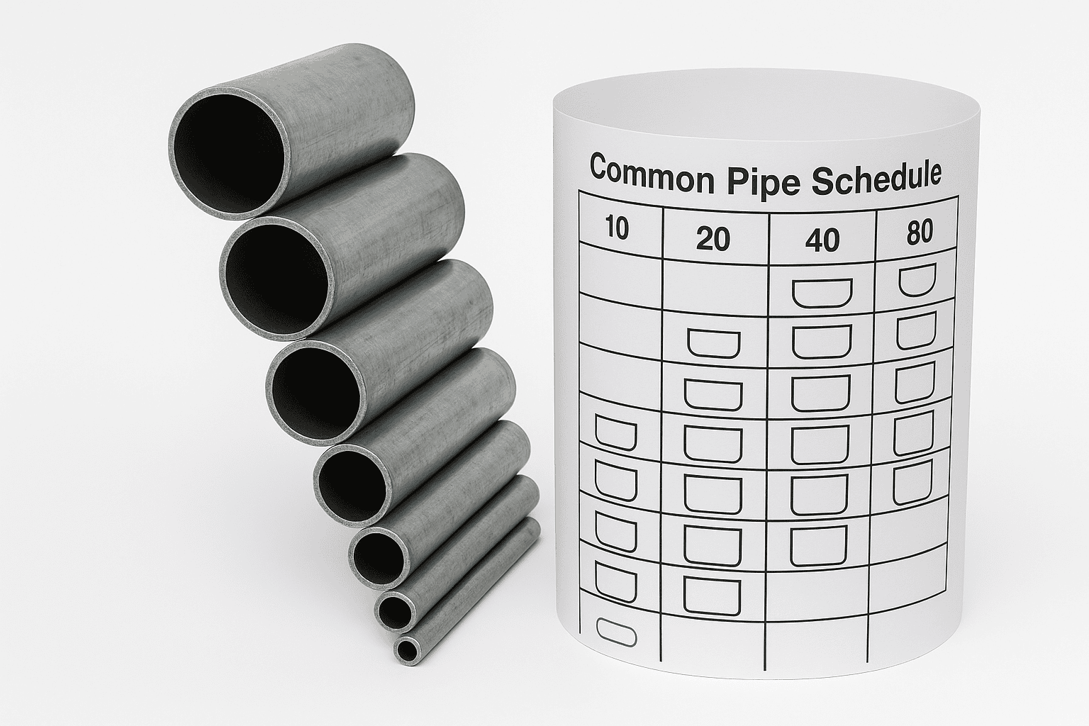
Pipe Size Chart & Common Pipe Schedule
Pipe Schedule Explained: How Wall Thickness Changes with Schedule Number
A maintenance engineer replacing a corroded 2-inch carbon steel line in a boiler room often faces a familiar constraint: the existing flanges and valves must stay in place. The outside diameter remains fixed for a given NPS, so the engineer selects the same NPS and then chooses a schedule that meets pressure and corrosion requirements without changing the mating components.
Pipe schedule describes wall thickness, which drives both pressure capacity and internal flow area. For example, NPS 2 steel pipe keeps an outside diameter of 2.375 inches (60.3 mm), but the wall thickness changes with schedule. Under ASME B36.10M, NPS 2 Schedule 40 typically uses a 0.154-inch (3.91 mm) wall, while Schedule 80 typically uses a 0.218-inch (5.54 mm) wall. That increase of 0.064 inches (1.63 mm) per wall reduces the inside diameter by about 0.128 inches (3.26 mm) in total, which can raise velocity and friction losses in long runs.
The schedule number does not scale linearly across sizes, and it does not represent a single thickness value. Instead, it groups thicknesses that align with pressure design practice. Engineers usually confirm suitability by checking the pipe’s pressure rating against the design conditions using ASME B31.3 (process piping) or the applicable code, then verifying that the selected schedule still supports the required flow rate.
In broader applications, schedule selection becomes a balancing act between strength, hydraulics, weight, and cost. A higher schedule can provide extra corrosion allowance and higher allowable pressure, but it also increases mass per metre and can reduce pump efficiency if the smaller bore forces higher velocities. Matching NPS preserves fit-up; choosing the right schedule preserves performance and safety.
Common Pipe Schedules Compared (Sch 10, 20, 40, 80, 160): Typical Uses and Limits
Schedule 10 and Schedule 160 sit at opposite ends of the same design choice: lower wall thickness for weight and cost control versus higher wall thickness for pressure margin and mechanical robustness. For a fixed NPS, the outside diameter stays constant, while the schedule changes the wall and the internal bore. As a result, Sch 10 typically suits low-to-moderate pressure services, while Sch 160 targets high-pressure or high-risk duties where deformation and corrosion allowance matter.
Option A (lower schedules: Sch 10 and Sch 20) prioritises flow area and handling. For NPS 2, Sch 10 has a 0.109 inch (2.77 mm) wall, while Sch 20 increases to 0.125 inch (3.18 mm) (ASME B36.10M). Option B (higher schedules: Sch 80 and Sch 160) prioritises strength and reserve thickness; for NPS 2, Sch 80 uses 0.218 inch (5.54 mm) and Sch 160 uses 0.344 inch (8.74 mm) (ASME B36.10M). Sch 40 often sits between these extremes and remains a common default for general industrial piping.
| Schedule | Relative wall thickness | Typical use profile | Common limiting factors |
|---|---|---|---|
| Sch 10 | Thin | Low-pressure utilities, drainage, ventilation, non-critical process lines | Lower pressure capacity; reduced corrosion allowance |
| Sch 20 | Light-to-medium | Moderate-pressure services where weight still matters | Less common availability than Sch 40 in some markets |
| Sch 40 | Medium | General-purpose industrial piping, water, compressed air, many process duties | May require upsizing for high pressure or severe corrosion |
| Sch 80 | Thick | Higher-pressure lines, steam, hydraulic returns, harsher mechanical environments | Reduced internal diameter; higher weight and cost |
| Sch 160 | Very thick | High-pressure or high-consequence services, severe corrosion allowance designs | Significant bore reduction; fabrication and welding heat input control |
These differences carry practical implications beyond pressure. Thicker schedules reduce internal diameter, which can increase velocity and friction losses; engineers often verify this with a Hazen–Williams or Darcy–Weisbach check during sizing. Thicker walls also increase mass, which raises support loads and can change thermal expansion behaviour, especially on steam lines. For pressure design, teams typically reference ASME B31.3 and confirm schedule availability against ASME B36.10M (carbon steel) or ASME B36.19M (stainless steel).
Pipe Size Chart: NPS/DN, Outside Diameter, Wall Thickness, and Inside Diameter
Specification errors often start with a measurable mismatch: a contractor orders “2-inch pipe” expecting a 2.000-inch bore, then discovers the installed inside diameter changes by schedule. On an NPS 2 line, the outside diameter stays fixed at 2.375 inches (60.3 mm), but the inside diameter can vary by more than 0.200 inches across common schedules, which affects flow, pressure drop, and valve sizing. This problem shows up during tie-ins, pump replacements, and capacity upgrades, where a small bore change can push velocity beyond design limits.
A pipe size chart resolves this by putting four values side-by-side: NPS/DN (designation), outside diameter (OD), wall thickness (WT), and inside diameter (ID). Engineers treat OD as the compatibility dimension for fittings and flanges, then use WT to confirm pressure and corrosion allowance, and ID to validate hydraulics. For dimensional standards, use ASME B36.10M for carbon steel and ASME B36.19M for stainless steel.
Apply the chart with a repeatable method. Start by confirming the designation stamped on the pipe or drawings (for example, NPS 2 / DN 50). Next, read the OD from the standard table; for NPS 2, OD remains 2.375 inches regardless of schedule. Then select the schedule and take the wall thickness from the chart; for NPS 2, Sch 40 has a 0.154-inch wall, while Sch 80 has a 0.218-inch wall (ASME). Calculate ID as OD minus two times WT: Sch 40 ID equals 2.375 − 2×0.154 = 2.067 inches; Sch 80 ID equals 2.375 − 2×0.218 = 1.939 inches.
This approach produces predictable results: you keep OD compatibility with existing components, quantify the bore change (0.128 inches between Sch 40 and Sch 80 on NPS 2), and reduce rework caused by incorrect assumptions about “nominal” size. It also supports faster hydraulic checks because the chart provides the exact ID needed for velocity and pressure-drop calculations.
NPS to DN & Outside Diameter (OD) Reference
| NPS (in) | DN | OD (in) | OD (mm) | Notes |
|---|---|---|---|---|
| 1/8 | 6 | 0.410 | 10.30 | For NPS ≤ 12, OD is fixed and not equal to NPS. |
| 1/4 | 8 | 0.540 | 13.70 | For NPS ≤ 12, OD is fixed and not equal to NPS. |
| 3/8 | 10 | 0.680 | 17.10 | For NPS ≤ 12, OD is fixed and not equal to NPS. |
| 1/2 | 15 | 0.840 | 21.30 | For NPS ≤ 12, OD is fixed and not equal to NPS. |
| 3/4 | 20 | 1.050 | 26.70 | For NPS ≤ 12, OD is fixed and not equal to NPS. |
| 1 | 25 | 1.320 | 33.40 | For NPS ≤ 12, OD is fixed and not equal to NPS. |
| 1 1/4 | 32 | 1.660 | 42.20 | For NPS ≤ 12, OD is fixed and not equal to NPS. |
| 1 1/2 | 40 | 1.900 | 48.30 | For NPS ≤ 12, OD is fixed and not equal to NPS. |
| 2 | 50 | 2.375 | 60.30 | For NPS ≤ 12, OD is fixed and not equal to NPS. |
| 2 1/2 | 65 | 2.875 | 73.00 | For NPS ≤ 12, OD is fixed and not equal to NPS. |
| 3 | 80 | 3.500 | 88.90 | For NPS ≤ 12, OD is fixed and not equal to NPS. |
| 3 1/2 | 90 | 4.000 | 101.60 | For NPS ≤ 12, OD is fixed and not equal to NPS. |
| 4 | 100 | 4.500 | 114.30 | For NPS ≤ 12, OD is fixed and not equal to NPS. |
| 5 | 125 | 5.563 | 141.30 | For NPS ≤ 12, OD is fixed and not equal to NPS. |
| 6 | 150 | 6.625 | 168.30 | For NPS ≤ 12, OD is fixed and not equal to NPS. |
| 8 | 200 | 8.625 | 219.10 | For NPS ≤ 12, OD is fixed and not equal to NPS. |
| 10 | 250 | 10.750 | 273.00 | For NPS ≤ 12, OD is fixed and not equal to NPS. |
| 12 | 300 | 12.750 | 323.80 | For NPS ≤ 12, OD is fixed and not equal to NPS. |
| 14 | 350 | 14.000 | 355.60 | For NPS ≥ 14, OD ≈ NPS. |
| 16 | 400 | 16.000 | 406.40 | For NPS ≥ 14, OD ≈ NPS. |
| 18 | 450 | 18.000 | 457.00 | For NPS ≥ 14, OD ≈ NPS. |
| 20 | 500 | 20.000 | 508.00 | For NPS ≥ 14, OD ≈ NPS. |
| 24 | 600 | 24.000 | 610.00 | For NPS ≥ 14, OD ≈ NPS. |
Schedule 40 Pipe Dimensions Chart (OD, Wall, ID, Weight)
| NPS (in) | DN | OD (in) | OD (mm) | Wall (in) | Wall (mm) | ID (in) | ID (mm) | Weight (lb/ft) | Weight (kg/m) |
|---|---|---|---|---|---|---|---|---|---|
| 1/8 | 6 | 0.410 | 10.30 | 0.068 | 1.73 | 0.274 | 6.84 | 0.24 | 0.37 |
| 1/4 | 8 | 0.540 | 13.70 | 0.088 | 2.24 | 0.364 | 9.22 | 0.42 | 0.63 |
| 3/8 | 10 | 0.680 | 17.10 | 0.091 | 2.31 | 0.498 | 12.48 | 0.57 | 0.84 |
| 1/2 | 15 | 0.840 | 21.30 | 0.109 | 2.77 | 0.622 | 15.76 | 0.85 | 1.27 |
| 3/4 | 20 | 1.050 | 26.70 | 0.113 | 2.87 | 0.824 | 20.96 | 1.13 | 1.69 |
| 1 | 25 | 1.320 | 33.40 | 0.133 | 3.38 | 1.054 | 26.64 | 1.68 | 2.50 |
| 1 1/4 | 32 | 1.660 | 42.20 | 0.140 | 3.56 | 1.380 | 35.08 | 2.27 | 3.39 |
| 1 1/2 | 40 | 1.900 | 48.30 | 0.145 | 3.68 | 1.610 | 40.94 | 2.72 | 4.05 |
| 2 | 50 | 2.375 | 60.30 | 0.154 | 3.91 | 2.067 | 52.48 | 3.65 | 5.44 |
| 2 1/2 | 65 | 2.875 | 73.00 | 0.203 | 5.16 | 2.469 | 62.68 | 5.79 | 8.63 |
| 3 | 80 | 3.500 | 88.90 | 0.216 | 5.49 | 3.068 | 77.92 | 7.58 | 11.29 |
| 3 1/2 | 90 | 4.000 | 101.60 | 0.226 | 5.74 | 3.548 | 90.12 | 9.11 | 13.57 |
| 4 | 100 | 4.500 | 114.30 | 0.237 | 6.02 | 4.026 | 102.26 | 10.79 | 16.07 |
| 5 | 125 | 5.563 | 141.30 | 0.258 | 6.55 | 5.047 | 128.20 | 14.62 | 21.77 |
| 6 | 150 | 6.625 | 168.30 | 0.280 | 7.11 | 6.065 | 154.08 | 18.97 | 28.26 |
| 8 | 200 | 8.625 | 219.10 | 0.322 | 8.18 | 7.981 | 202.74 | 28.55 | 42.55 |
| 10 | 250 | 10.750 | 273.00 | 0.365 | 9.27 | 10.020 | 254.46 | 40.48 | 60.31 |
| 12 | 300 | 12.750 | 323.80 | 0.406 | 10.31 | 11.938 | 303.18 | 53.52 | 79.73 |
| 14 | 350 | 14.000 | 355.60 | 0.437 | 11.13 | 13.126 | 333.34 | 54.57 | 94.55 |
| 16 | 400 | 16.000 | 406.40 | 0.500 | 12.70 | 15.000 | 381.00 | 82.77 | 123.30 |
| 18 | 450 | 18.000 | 457.00 | 0.562 | 14.27 | 16.876 | 428.46 | 104.67 | 155.80 |
| 20 | 500 | 20.000 | 508.00 | 0.594 | 15.09 | 18.812 | 477.82 | 123.11 | 183.42 |
| 24 | 600 | 24.000 | 610.00 | 0.688 | 17.48 | 22.624 | 575.04 | 171.29 | 255.41 |
Schedule 80 Pipe Dimensions Chart (OD, Wall, ID, Weight)
| NPS (in) | DN | OD (in) | OD (mm) | Wall (in) | Wall (mm) | ID (in) | ID (mm) | Weight (lb/ft) | Weight (kg/m) |
|---|---|---|---|---|---|---|---|---|---|
| 1/8 | 6 | 0.410 | 10.30 | 0.095 | 2.41 | 0.220 | 5.48 | 0.31 | 0.47 |
| 1/4 | 8 | 0.540 | 13.70 | 0.119 | 3.02 | 0.302 | 7.66 | 0.54 | 0.80 |
| 3/8 | 10 | 0.680 | 17.10 | 0.126 | 3.20 | 0.428 | 10.70 | 0.74 | 1.10 |
| 1/2 | 15 | 0.840 | 21.30 | 0.147 | 3.73 | 0.546 | 13.84 | 1.09 | 1.62 |
| 3/4 | 20 | 1.050 | 26.70 | 0.154 | 3.91 | 0.742 | 18.88 | 1.47 | 2.20 |
| 1 | 25 | 1.320 | 33.40 | 0.179 | 4.55 | 0.962 | 24.30 | 2.17 | 3.24 |
| 1 1/4 | 32 | 1.660 | 42.20 | 0.191 | 4.85 | 1.278 | 32.50 | 3.00 | 4.47 |
| 1 1/2 | 40 | 1.900 | 48.30 | 0.200 | 5.08 | 1.500 | 38.14 | 3.63 | 5.41 |
| 2 | 50 | 2.375 | 60.30 | 0.218 | 5.54 | 1.939 | 49.22 | 5.02 | 7.48 |
| 2 1/2 | 65 | 2.875 | 73.00 | 0.276 | 7.01 | 2.323 | 58.98 | 7.66 | 11.41 |
| 3 | 80 | 3.500 | 88.90 | 0.300 | 7.62 | 2.900 | 73.66 | 10.25 | 15.27 |
| 3 1/2 | 90 | 4.000 | 101.60 | 0.318 | 8.08 | 3.364 | 85.44 | 12.50 | 18.63 |
| 4 | 100 | 4.500 | 114.30 | 0.337 | 8.56 | 3.826 | 97.18 | 14.98 | 22.32 |
| 5 | 125 | 5.563 | 141.30 | 0.375 | 9.53 | 4.813 | 122.24 | 20.78 | 30.97 |
| 6 | 150 | 6.625 | 168.30 | 0.432 | 10.97 | 5.761 | 146.36 | 28.57 | 42.56 |
| 8 | 200 | 8.625 | 219.10 | 0.500 | 12.70 | 7.625 | 193.70 | 43.39 | 64.64 |
| 10 | 250 | 10.750 | 273.00 | 0.594 | 15.09 | 9.562 | 242.82 | 64.43 | 96.01 |
| 12 | 300 | 12.750 | 323.80 | 0.688 | 17.48 | 11.374 | 288.84 | 88.63 | 132.08 |
| 14 | 350 | 14.000 | 355.60 | 0.750 | 19.05 | 12.500 | 317.50 | 106.13 | 158.10 |
| 16 | 400 | 16.000 | 406.40 | 0.844 | 21.44 | 14.312 | 363.52 | 136.61 | 203.53 |
| 18 | 450 | 18.000 | 457.00 | 0.938 | 23.83 | 16.124 | 409.34 | 170.92 | 254.55 |
| 20 | 500 | 20.000 | 508.00 | 1.031 | 26.19 | 17.938 | 455.62 | 208.87 | 311.17 |
| 24 | 600 | 24.000 | 610.00 | 1.125 | 30.96 | 21.750 | 548.08 | 296.58 | 442.08 |
How to Select Pipe Size and Schedule for Pressure, Flow Rate, and Material
For water at 20 °C, a 10 m run carrying 1.0 L/s in a 50 mm internal diameter pipe typically produces about 0.8 m/s velocity, while the same flow in a 25 mm internal diameter pipe rises to about 2.0 m/s. That change in velocity increases friction losses sharply, because pressure drop scales roughly with the square of velocity in common design calculations. As a result, pipe size selection controls pump head, energy use, and noise long before material limits become critical.
Start by fixing the required flow rate and an acceptable pressure drop, then choose an internal diameter that keeps velocity within the service target. For many building-services water systems, designers often aim for roughly 0.6–2.0 m/s to balance pipe size against pumping cost; exceeding that range can accelerate erosion at fittings and raise audible turbulence. After selecting a candidate bore, verify the pressure rating by matching the schedule to the design pressure and temperature, using the applicable code tables and material data.
Schedule choice then becomes a trade-off between pressure capacity, corrosion allowance, and hydraulic performance. Increasing wall thickness reduces internal diameter, which increases velocity and pressure drop at the same flow. On an NPS 2 line, moving from Sch 40 to Sch 80 reduces the internal diameter from about 2.067 in (52.5 mm) to about 1.939 in (49.3 mm), cutting flow area by roughly 12% and increasing velocity by about 14% for the same duty. That shift can push a marginal design over pump limits even when the pressure rating improves.
Material selection sets the allowable stress and corrosion behaviour that schedule alone cannot solve. Carbon steel, stainless steel, and thermoplastics each change the pressure–temperature envelope and joining method, which affects practical limits on wall thickness and installation. Confirm dimensions and schedules against the governing standards, such as ASME B36.10M for steel pipe, and validate pressure design using the relevant piping code for the service.
Standards and Reference Tables: ASME B36.10M, ASME B36.19M, and ISO DN
A project engineer ordering stainless pipe for a food-processing skid often sees two labels for the same line: “DN50” on the P&ID and “NPS 2” on a supplier quote. The skid must connect to existing hygienic valves, so the engineer needs a standard that fixes the outside diameter and a reference table that confirms the wall thickness for the chosen schedule. That is where ASME dimensional standards and ISO DN designations prevent expensive mismatches at the flange face.
ASME B36.10M defines outside diameters and wall thicknesses for welded and seamless wrought steel pipe, commonly used for carbon steel and alloy steel services. For example, NPS 2 has a fixed outside diameter of 2.375 in (60.3 mm), and Schedule 40 sets a nominal wall thickness of 0.154 in (3.91 mm). Because the outside diameter stays constant, the engineer can change schedule for pressure or corrosion allowance without changing mating components, provided the standard remains consistent across the bill of materials.
ASME B36.19M covers stainless steel pipe dimensions and includes common “S” schedules used in process industries. On NPS 2, Schedule 10S lists a nominal wall thickness of 0.109 in (2.77 mm), while Schedule 40S lists 0.154 in (3.91 mm). That difference changes the internal diameter by roughly 0.090 in (about 2.3 mm), which can shift velocity and pressure drop enough to affect pump selection on compact skids.
ISO DN acts as a nominal metric size designation rather than a direct measurement. ISO 6708 defines DN as a dimensionless number used to reference compatible component sizes. In practice, DN50 commonly maps to NPS 2 for many piping components, but engineers should still verify the governing dimensional table (ASME or ISO) before ordering, because compatibility depends on the specified standard, not the label alone.
Frequently Asked Questions
What do NPS and DN mean on a pipe size chart?
NPS means Nominal Pipe Size, a North American sizing label based on a nominal (name) diameter, not the exact outside diameter. DN means Diamètre Nominal, the metric equivalent expressed as a whole number in millimetres. For example, NPS 2 roughly corresponds to DN 50, while the actual outside diameter is 60.3 mm.
How does nominal pipe size (NPS) differ from the pipe’s actual outside diameter (OD)?
Nominal pipe size (NPS) is a standard designation, not a measured diameter. For NPS 14 and smaller, the actual outside diameter (OD) stays fixed for each NPS, while wall thickness changes by schedule. For NPS 14 and larger, OD matches the NPS value in inches (for example, NPS 16 has a 16.000-inch OD).
What does a pipe schedule number (such as Schedule 40 or Schedule 80) indicate about wall thickness?
A pipe schedule number indicates the pipe’s wall thickness relative to its nominal size. For the same nominal diameter, a higher schedule means a thicker wall and a smaller internal diameter. For example, Schedule 80 has a thicker wall than Schedule 40 at the same nominal pipe size, increasing pressure capacity and weight.
How do you calculate a pipe’s inside diameter (ID) from OD and wall thickness values in a schedule chart?
Calculate inside diameter (ID) by subtracting twice the wall thickness from the outside diameter (OD): ID = OD − 2 × wall thickness. Use consistent units (mm or inches). Example: OD 60.3 mm with 3.9 mm wall gives ID 52.5 mm (60.3 − 7.8). Round to match the schedule chart precision.
Which pipe schedules are most commonly used for residential plumbing compared with industrial applications?
Residential plumbing most often uses Schedule 40 PVC for cold-water drainage and venting, plus Schedule 40 or Schedule 80 CPVC for hot and cold supply lines (typically 15–50 mm). Industrial systems more often specify Schedule 80 and Schedule 160 for higher pressure and abrasion resistance, with larger diameters (50–600 mm) and higher design pressures.
How do you convert between imperial pipe sizes (inches) and metric equivalents (DN and millimetres)?
Convert by matching the imperial NPS (nominal pipe size, inches) to the nearest DN (nominal diameter, millimetres) using a standard chart; DN is a designation, not the measured diameter. Use OD for accuracy: NPS 1/2 has 21.3 mm OD (DN15), NPS 1 has 33.4 mm OD (DN25), NPS 2 has 60.3 mm OD (DN50).
How does changing pipe schedule affect flow capacity and pressure rating for the same NPS?
For the same NPS, a higher schedule means a thicker wall and smaller internal diameter. That reduces flow capacity because cross-sectional area drops; for example, a 2-inch pipe ID falls from about 2.067 inches (Sch 40) to 1.939 inches (Sch 80), cutting area by roughly 12%. Pressure rating rises because thicker walls withstand higher internal pressure.