
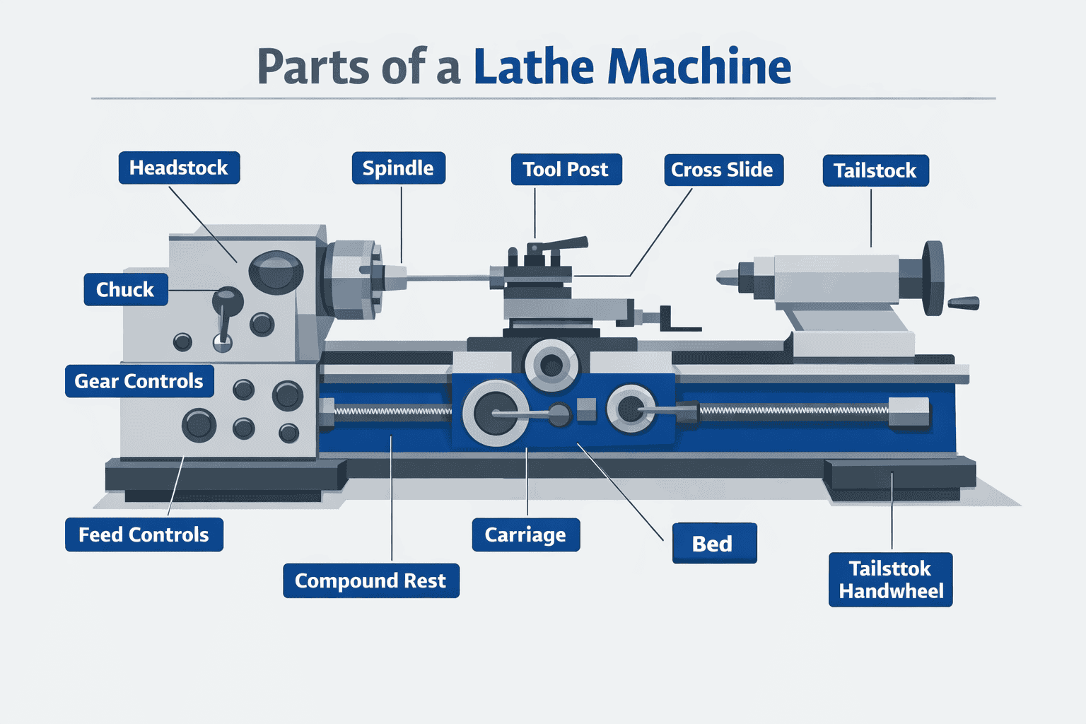
A lathe machine consists of several core components — including the headstock, tailstock, carriage, bed, and chuck — each performing a distinct role in rotating a workpiece against a cutting tool to shape it. Together, these parts control speed, feed rate, tool position, and workpiece support across turning, facing, threading, and boring operations. This article examines each major component, explains its mechanical function, and describes how it contributes to accurate, repeatable machining.
Key takeaways
- Inspect the bed’s precision-ground ways before mounting any workpiece to prevent alignment errors.
- Spindle speed must match the material — too fast degrades cutting edges on hardened steel.
- The tailstock prevents workpiece flex on long cuts; without it, you get a convex profile.
- Set and lock the compound rest angle before starting a taper cut to eliminate play.
- Re-engaging the half-nut at the wrong position on a multi-pass thread cut ruins the groove.
- Bed ways deteriorate first, followed by cross-slide gibs loosening, then spindle bearing play increasing.
- Match component grade to actual precision requirements — underspecifying causes errors that accumulate across every pass.
The Bed: Foundation and Alignment of the Lathe
Inspect the bed before mounting any workpiece — misalignment here propagates error through every subsequent cut. The bed is the horizontal base that runs the full length of the lathe, and every major component, including the headstock, tailstock, and carriage, mounts directly to it. Its precision-ground ways (the raised guiding surfaces) keep the carriage moving in a straight, repeatable line parallel to the spindle axis.
Cast iron is the standard material because it dampens vibration effectively and resists deformation under sustained cutting loads. Hardened and ground ways reduce wear, but they require regular cleaning and light oiling to maintain accuracy over time. Even small chips or swarf left on the ways can score the surface and introduce lateral drift into longitudinal cuts.
- Effectively dampens vibration during cutting operations
- Resists deformation under sustained cutting loads
- Hardened and ground ways reduce long-term wear
- Provides a stable, rigid foundation for all major components
- Precision-ground ways keep the carriage moving in a straight, repeatable line
- Requires regular cleaning to prevent swarf and chip buildup on ways
- Needs light oiling consistently to maintain accuracy over time
- Even small chips left on ways can score the surface and cause lateral drift
- Longer beds demand greater casting rigidity to prevent flex under load
- Misalignment in the bed propagates error through every subsequent cut
The distance between centres — a key lathe specification listed by resources such as Engineering Designer — is measured along the bed and determines the maximum workpiece length the machine can accommodate. A longer bed allows larger work but demands more rigidity in the casting to prevent flex under load.
The Headstock: Spindle Drive and Speed Control
Spindle speed directly determines surface finish and tool life. Run too fast on hardened steel and the cutting edge degrades within minutes; too slow on aluminium and the tool rubs rather than cuts. The headstock houses the spindle, its support bearings, and the drive mechanism controlling rotational speed.
The spindle is a hollow, precision-ground shaft whose through-bore allows long bar stock to pass completely through the machine — essential for high-volume turning. The nose accepts chucks, faceplates, and collet holders via a threaded or cam-lock fitting. Gear-driven headstocks deliver more torque at low speeds for heavy cuts; variable-speed inverter drives offer finer control for finishing passes and non-ferrous work.
| Feature | Gear-Driven Headstock | Variable-Speed Inverter Drive |
|---|---|---|
| Torque at Low Speed | High — suited for heavy cuts | Moderate — better for finishing |
| Speed Control | Step changes via gear selection | Fine, continuous adjustment |
| Best Use Case | Heavy-duty turning on steel | Finishing passes and non-ferrous work |
| Complexity | Robust but mechanically complex | Electronically controlled, fewer moving parts |
Preloaded taper roller or angular contact bearings support the spindle and must be kept free of play. Any radial runout transfers directly to the workpiece as dimensional error. On production lathes, spindle runout is typically held within 0.002 mm — the threshold for maintaining precision tolerances without corrective passes.
The Tailstock: Support, Drilling, and Axial Positioning
The tailstock supports the free end of long or slender workpieces through a centre point in its morse taper bore. Without that support, cutting forces flex the workpiece, producing a convex profile instead of a true cylinder. A drill chuck or live centre mounts directly in the taper, making it the primary station for centre drilling, reaming, and supported turning.
The quill — a sliding barrel inside the body — advances by turning the handwheel and locks at a set depth for precise axial positioning. Lateral offset screws shift the body sideways: intentional for taper turning, but for parallel turning the tailstock centreline must align exactly with the spindle centreline. Bring a tailstock centre up to a test bar and measure deviation with a dial indicator — 0.05 mm of offset produces a noticeable taper on longer components.
Clamp the tailstock firmly before any cut. A loose tailstock walks under drilling pressure, enlarging holes unevenly and pulling the drill off-axis. Re-check the clamp bolt whenever the tailstock is repositioned.
The Carriage: Tool Movement and Cutting Control
The carriage travels along the bed ways and translates handwheel inputs and leadscrew drive into controlled movement. It has four parts: the saddle moves longitudinally along the bed; the cross-slide sits above it and controls depth of cut; the compound rest swivels for taper turning; and the tool post clamps the cutting tool.
Set the compound rest angle before starting a taper cut and lock the gibs fully — any play introduces chatter. Cross-slide gibs should be snug without binding. Check both before each session, as vibration from previous cuts can loosen them gradually.
When threading, confirm the half-nut is engaged before starting the pass. Disengaging at the wrong point loses thread synchronisation and requires restarting from scratch. For general turning between centres, use the power feed through the apron rather than hand feeding — it eliminates variation in hand pressure and produces a more consistent surface finish.
The Feed and Lead Screw Mechanism: Automated Traverse and Threading
Thread pitch accuracy depends on how reliably the carriage moves relative to spindle rotation. The lead screw — a precision-ground threaded shaft running the full bed length — controls this directly. Engaging the half-nut lever locks the carriage to a fixed advance rate per spindle revolution. Re-engaging at the wrong position on a multi-pass cut causes the tool to miss the original groove entirely.
The feed rod handles general turning and facing passes through a friction clutch in the apron, protecting the mechanism from roughing overloads. Using it for plain turning preserves lead screw condition; repeated non-threading engagement accelerates flank wear and reduces thread-cutting precision over time.
Both shafts draw drive from the quick-change gearbox. Selecting different gear combinations changes the advance rate without swapping change gears, and most metric and imperial pitches are accessible directly from the index plate.
Backlash in the half-nut or worn lead screw threads causes pitch errors no cutting technique can correct. Measure a test thread against a known pitch gauge periodically — any deviation beyond tolerance means the screw needs replacement before precision work continues.
Choosing and Maintaining Lathe Components for Precision and Longevity
Match component grade to the work the lathe will consistently perform. Precision grinding demands hardened and ground ways, preloaded spindle bearings, and a rigid tool post. Specifying below the actual requirement produces errors that accumulate across every pass.
Wear follows a predictable sequence: bed ways deteriorate first, then cross-slide gibs loosen, and spindle bearing play increases. Checking way flatness with a precision straight edge every six months catches bed wear before it affects diameter consistency. Tighten gib screws incrementally — over-tightening generates heat and accelerates wear.
Axial spindle play above 0.01 mm introduces facing error; lead screw backlash above 0.05 mm makes thread pitches unreliable. Both are measurable with a dial indicator. Spindle speed, feed rate, and dimensional error follow the same principles covered in understanding control systems in electrical engineering.
Way oil, spindle oil, and gear oil have different viscosity requirements — substituting one for another reduces film strength and shortens component life. Most manufacturer handbooks specify change intervals by operating hours, not calendar months, so track hours if the lathe runs intermittently.
Full List of Lathe Machine Parts
Refer to this list when specifying, inspecting, or replacing components — each part has a defined function, and gaps in understanding any one of them typically show up as dimensional error or premature wear.
Structural and Drive Components
- Bed — The precision-ground base that carries all major assemblies. Hardened and ground cast iron or fabricated steel construction. Way geometry determines alignment for every component mounted on it.
- Headstock — Fixed assembly at the left end of the bed. Houses the spindle, drive mechanism, and speed-change gearing or variable-speed unit. The spindle nose accepts chucks, faceplates, and collet adaptors.
- Spindle — Hollow, hardened shaft that transmits rotational drive to the workpiece. Through-bore diameter determines the maximum bar stock diameter the lathe can pass. Spindle nose taper (commonly MT3, MT4, or camlock) defines chuck compatibility.
- Tailstock — Slides along the bed and locks in position. The quill bore accepts Morse taper tooling. Offset adjustable for taper turning between centres.
- Lead screw — Precision-threaded shaft running the full bed length. Drives the carriage at a fixed rate per spindle revolution for threading operations.
- Feed rod — Separate shaft used for longitudinal and cross-feed during general turning. Does not engage the half-nut, so it cannot generate thread pitches.
- Gearbox (quick-change gearbox) — Mounted below the headstock on most engine lathes. Selects feed rate and thread pitch by shifting internal gears without disturbing the change gear set.
- Change gears — Interchangeable gears on the end of the lathe that set the ratio between spindle and lead screw rotation. Used on lathes without a quick-change gearbox, or for metric–imperial conversion.
Carriage Assembly Components
- Saddle — H-shaped casting that straddles the bed ways and moves longitudinally. Base for all upper carriage components.
- Apron — Front face of the saddle. Contains the half-nut mechanism, feed rod engagement clutch, handwheels, and feed direction controls.
- Cross-slide — Mounted on top of the saddle. Moves perpendicular to the spindle axis to control depth of cut and facing operations.
- Compound rest (top slide) — Swivels on the cross-slide. Adjusted to any angle for short taper turning and precise axial tool positioning. Has its own graduated dial and lead screw.
- Tool post — Clamping device at the top of the compound rest. Four-way indexing posts suit production turning; quick-change tool posts (such as those in the Aloris or Dickson style) allow faster insert changes with repeatable height.
- Gibs — Tapered or flat adjustment strips fitted between sliding surfaces on the cross-slide and compound rest. Tightening them removes play; over-tightening causes binding and accelerated wear.
Workholding and Auxiliary Components
- Chuck — Three-jaw self-centring chucks grip round and hexagonal stock. Four-jaw independent chucks allow off-centre and irregular workpiece mounting.
- Faceplate — Large flat disc threaded to the spindle nose. Used for workpieces too large or irregular for a chuck.
- Steady rest (fixed steady) — Bolts to the bed and supports long workpieces at an intermediate point via three adjustable bronze or roller contact pads.
- Follower rest (travelling steady) — Mounts on the saddle and travels with the carriage, providing support directly behind the cutting zone on slender shafts.
- Centre (dead or live) — Mounted in tailstock or headstock to support workpieces between centres. Live centres (rotating on internal bearings) suit higher speeds; dead centres require lubrication.
- Drive plate and lathe dog — Used with between-centres turning. The drive plate rotates with the spindle; the lathe dog clamps to the workpiece and engages a pin on the plate.
- Splash guard and chip tray — Contain coolant and swarf. Chip management directly affects way lubrication; abrasive swarf left on unprotected ways accelerates wear measurably.
Frequently Asked Questions
What are the main parts of a lathe machine and what does each one do?
A lathe machine has several core components, each handling a specific role in shaping workpieces. The bed provides the foundation; the headstock drives rotation; the tailstock supports the workpiece opposite end. The carriage moves the cutting tool, while the chuck holds the material securely in place.
What is the function of the headstock on a lathe machine?
The headstock is the power centre of the lathe. It houses the main spindle, drive gears, and speed controls that rotate the workpiece. All cutting operations depend on the torque and rotational speed the headstock delivers through the spindle to the chuck or faceplate.
How does the carriage help control cutting operations on a lathe?
Slide the carriage along the bed to position the cutting tool precisely against the workpiece. It holds the tool post, cross-slide, and compound rest, giving the operator control over depth of cut and feed direction. Together, these components allow accurate longitudinal and transverse movement during turning operations.
What role does the tailstock play in lathe machine work?
Unlike the headstock, the tailstock does not rotate. It sits at the opposite end of the bed and supports the free end of long workpieces, preventing deflection under cutting pressure. It also holds tools such as drill bits and reamers for centre drilling and boring operations along the lathe’s axis.
Why is the chuck important in a lathe machine?
The chuck grips the workpiece directly, making it the primary point of contact between the material and the lathe’s rotational force. Without secure clamping, the workpiece shifts under cutting pressure, producing inaccurate dimensions. Three-jaw chucks centre round stock automatically, while four-jaw versions handle irregular shapes.